
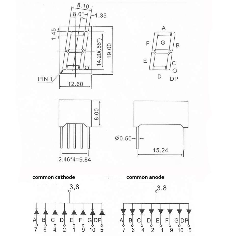
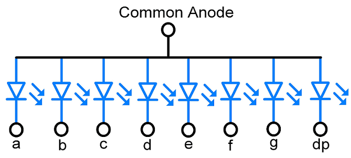
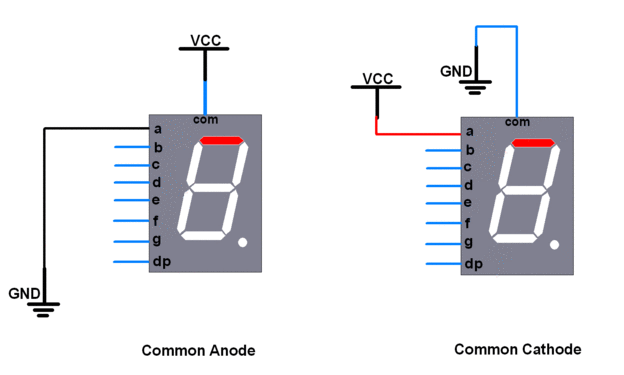
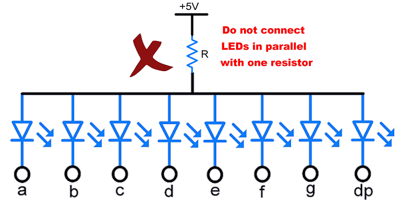
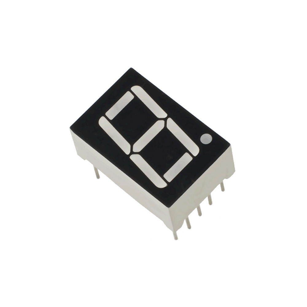
In common anode display, all anode pins are connected together to VCC and LEDs are controlled via cathode terminals. It means to turn ON LED (segment), we have to make that cathode pin logic LOW or Ground.
Following demonstration will show the working of above configuration,
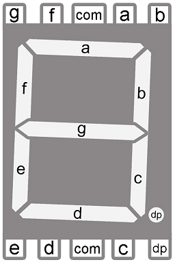
Pin Diagram of 7-Segment Display
Note: Please refer required voltage, absolute max current and forward voltage drop of the segment from the datasheet.
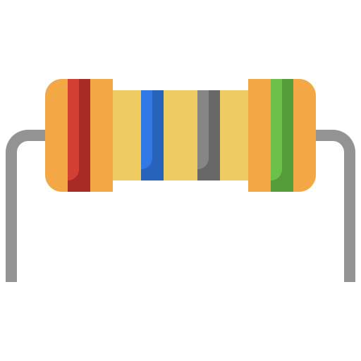
Calculation of Resistor Value
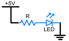
R = (VS – VLED) / ILED
Where,
R = Resistor in series with LED.
Vs = Source voltage.
VLED = LED forward voltage drop.
ILED = LED forward current.
Example
Normally voltage is 5volt and abs. max. current is about 20mA to 25mA. Let’s take current ILED = 10mA (considering safer margin) as 10mA is sufficient to glow the segment.
VS = 5V and VLED = 1.7V then resistor value is.
R = (5 – 1.7)/ 0.010 = 300 Ohm

المختــرع المجنــون © جميـــع الحقــوق محفوظــة