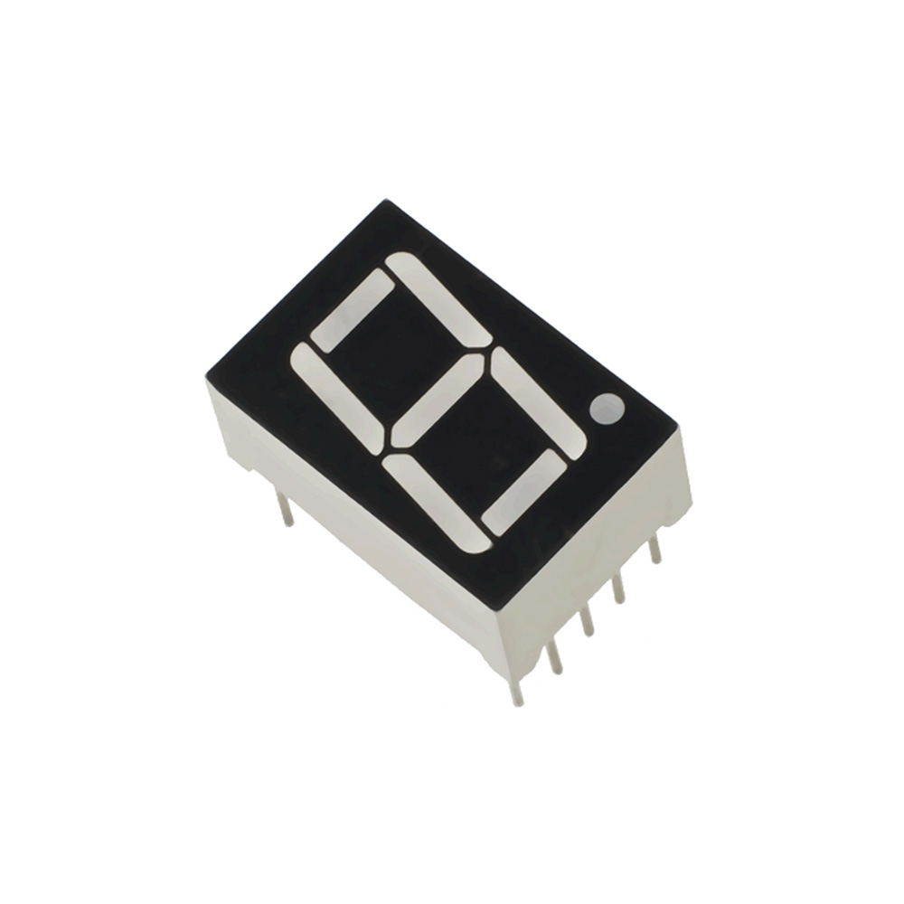
- 7-segment LED displays are formed by LED segments. It is used to display numerical values from 0 to 9. One more segment is also present there which is used as a decimal point.
7-Segment Display
- In 7-segment displays, there are two types, common anode and common cathode.
Common Cathode (CC)
In a common cathode display, all cathode pins are connected together and LEDs are controlled via an anode terminal. It means to turn ON the LED (segment), we have to apply proper voltage to the anode pin.
The following demonstration will show the working of the above configuration,
- The 7-segment display has a total of 10 pins.
- The common pin (com) is connected either in a common anode or a common cathode configuration.
Pin Diagram of 7-Segment Display
- We have to connect the resistor to each segment individually.
- Avoid LED’s connection in parallel with one resistor, because each LED segment doesn’t have the same forward voltage drop.
- If we connect one resistor to the parallel LEDs then some LEDs will glow and some will not. Because forward voltage drops are different for each LEDs, LEDs which are having lowest voltage drop across them will only glow. And though if we connect LEDs with ideally equal voltage drop, the current will get divided and brightness will get affected each time while switching the LEDs.
Calculation of Resistor Value
R = (VS – VLED) / ILED
Where,
R = Resistor in series with LED.
Vs = Source voltage.
VLED = LED forward voltage drop.
ILED = LED forward current.
Example
Normally voltage is 5volt and abs. max. current is about 20mA to 25mA. Let’s take current ILED = 10mA (considering safer margin) as 10mA is sufficient to glow the segment.
VS = 5V and VLED = 1.7V then the resistor value is.
R = (5 – 1.7)/ 0.010 = 300 Ohm